Key Features
-
Support for 1000Base-T1 (IEEE 802.3bp) and TC8
-
Highly automated and easy-to-use
-
Report generation with pass/fail results and fully annotated screenshot
-
Complete test solution including test fixture, signal generator & cables
-
Unique software recovery algorithm for the distortion test which greatly simplifies test setup
-
Supports all Group 1 PMA Tests
-
Output Droop
-
Master and Slave Timing Jitter
-
Clock Frequency
-
Distortion (with and without TX_TCLK access)
-
Power Spectral Density (PSD)
-
Peak Differential Output
-
Advanced debugging ability with "Stop on Test"
Automated Compliance Testing
QPHY-1000Base-T1 performs electrical compliance testing of the Physical Media Attachment (PMA) according to the 1000Base-T1 and TC8 specifications. Detailed connection diagrams ensure the proper setup and provide information about the required test pattern for each test. Upon completion of the test session, results are automatically compiled into a comprehensive report including screenshots.
Simplified Distortion Test
To properly perform the Distortion test, the DUT (Device Under Test), disturbing sine wave, and oscilloscope all need to be synchronized. In practice this proves to be a difficult task since the DUT’s TX_TCLK and the test equipment’s reference clock are at different frequencies. Teledyne LeCroy has developed a unique algorithm which performs software clock recovery on the Test Mode 4 signal, enabling the test to be completed without requiring a hardware frequency converter board.
Flexible Debug Environment
Using the “Stop on Test” feature, the user can pause testing after each individual test and observe the results. At that point, any of the oscilloscope’s tools can be leveraged for further debug and upon completion, testing can be seamlessly resumed with a click of a button.
Maximum Transmitter Output Droop
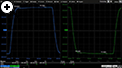
The output droop is calculated on both the “+1” and “-1” symbols in the Test Mode 6 waveform. The magnitude of the droop is measured with respect to an initial peak value 4 ns after the zero crossing (Vinit) and the value 16 ns after the initial peak value (Vdelay).
Transmitter Distortion
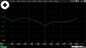
The peak distortion is determined by capturing output from the DUT while it is in Test Mode 4. The disturbing sine wave is removed and peak distortion is measured at equally spaced phases of the symbol period. To pass, the script must report less than 15 mV distortion for 10 records.
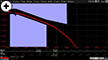
Transmitter Jitter Timing & Transmit Clock Frequency
The transmitter master timing and transmit clock frequency are tested while the DUT is in Test Mode 1 and 2. The slave and master jitter are measured by directly probing the DUT’s TX_TCLK.
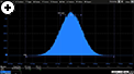
Transmitter PSD & Peak Differential Output
The Power Spectrum Density (PSD) of the transmitter is tested against the specified limits defined by the mask while the DUT is transmitting Test Mode 5. Using the oscilloscope for the PSD test removes the need to purchase a spectrum analyzer. The Test Mode 5 waveform is also used to test the peak differential output.