Gate and Delay Generators are designed to provide precisely timed logic windows and level
transitions. Applica tions employing Gate and Delay Generators may require that a logic
transition occur immediately and have a given duration. Others require that a delay elapse
prior to the logic transition, or that a precise gate be generated after some fixed delay.
All these functions of Gate Generator, Delay Generator, and Delayed Gate Generator are
performed by any LeCroy Gate and Delay Generator module.
LeCroy Gate and Delay Generators allow both manual and CAMAC programmability for gate
durations ranging from a few nanoseconds to several seconds. Both the 2323A and the 4222
can be used for burst mode operations with the TR8828D digitizer (see Application Note
2014).
Versatile Product Family - Two of the most popular modular instrumentation
standards used are NIM and CAMAC. Continuous manual control and high resolution
programmable digital delay adjustment are selected by choice of modules.
Minimum Dead Time - Any of these Gate and Delay Generators may be retriggered
immediately after the delay has elapsed.
Delayed Outputs - At the end of any gate, a delayed output issues a pulse.
Independent Gate and Delay Functions - Each LeCroy Gate and Delay Generator
provides precision gate lengths which can be used as a precision delay as well. Since each
unit has at least two such gate generators, one can be used as a delay which starts the
second generator that provides the gate signal.
Wide Dynamic Range - Ranges from under 100 nsec to 10 sec are provided by the Model
2323A. Model 4222 maintains 1 nsec resolution up to its range of 16.7 msec.
The Models 2323A and 4222 Gate and Delay Generators have their own unique advantages
that enhance their service in certain applications. For example, the 2323A can be
controlled manually, or programmed and has an ECL output for compatibility with LeCroy
ECLine trigger processor and data handling modules. The 4222 has four time generators in a
single-width module, making it a superior choice in high density systems where space is at
a premium.
Arbitrary gate widths are provided in the 2323A via a latch-mode operation where the gate
duration is determined by externally applied Start and Stop signals. Further versatility
is incorporated into this module by including a delayed output pulse which occurs at the
end of each gate output pulse and has a preset width.
Precision delayed gates can be produced with any LeCroy gate and delay generator module.
Gate signals can be used to set coincidence time windows, provide veto signals, or
generate fast clear signals after some preset delay. Latch Mode operation, available in
the Model 2323A, permits gating-off front-end electronics after receipt of a valid trigger
signal and maintaining this state until data acquisition is complete. For example,
discriminators may be vetoed immediately after the trigger electronics generate the ADC
gates. This ensures that no further ADC gates are generated.
Since each LeCroy gate and delay generator module has at least two independent generators,
one generator can be used as a precision delay. A delayed output pulse, occurring at the
end of the gate pulse, is applied to the Start of a second generator. The 2323A can be
configured in this manner.
The Model 2323A is a fully programmable Gate and Delay Generator packaged with 2 channels
in a double-width CAMAC module. Its Gate duration is programmable over the range 100 nsec
to 10 seconds, covering a dynamic range of eight orders of magnitude. Moreover, outputs as
short as 50 nsec can be selected at the expense of accuracy and stability. All settings
may be programmed under CAMAC control or via front-panel controls. The settings of the
instrument are battery backed-up, so the unit does not have to be reprogrammed after
turning the crate off/on or after a power failure. The 2323A offers excellent stability
and jitter properties with 0.2% of Full Scale accuracy in the gate setting.
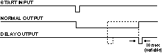
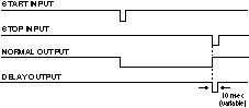
The 2323A offers both Start and Stop inputs. This allows the output pulse width to be
determined by the Start -Stop time difference in the latched mode or by the internal timer
in the preset mode. A Blanking NIM Level input causes a notch to be taken out of the gate,
equal in duration to the Blanking input. This is especially useful to gate off data
acquisition during spurious periods. Conversely, a NIM level OR input causes all outputs
to be set to True for the duration of the OR inputs.
The unit offers NIM and NIM level outputs equal in duration to the gate width selected. In
addition, a DELAY output is produced at the trailing edge of the Gate pulse. The 2323A
also provides a differential ECL output and a TTL output capable of driving a NIM Bin
Gate. Both the ECL and TTL outputs may be driven from either the Gate or Delay circuit.
These options are selected by board-mounted shorting plugs.
The Gate duration and the width of the Delayed output are both programmable under CAMAC
control. Each of the two channels are programmed independently. All values which are
loaded into the 2323A may also be read back via CAMAC. Programming the delay involves a
10-bit "mantissa" and a 3-bit "characteristic".
The Start input is normally configured to accept NIM level signals. A bridged high
impedance input is employed to allow the trigger of more than one channel of 2323A. The
front end of the Start input consists of a comparator circuit, factory adjusted to trigger
at -400 �50 mV. A front-panel accessed multiple turn potentiometer allows the user to
adjust the threshold over the range -3 V to +3 V. This allows the unit to be triggered by
NIM, ECL, TTL or other standard logic signals. A front-panel accessed switch selects
either the positive-going or negative-going edge as the trigger. The stop input accepts
NIM standard pulses.
Presettable Width Mode Diagram
Latch Mode Diagram
The LeCroy Model 4222, Quad, Wide Range, Gate and Delay Generator, produces long,
precise time delays and time intervals synchronously with a random Trigger input. All 4
channels of the 4222 are started by a common Trigger input. Each channel provides a
programmable time delay of up to 16.7 msec in 1 nsec increments. All programming is under
CAMAC control.
A set of side-panel switches permits the selection of coupled window outputs for channels
1 and 2, or 3 and 4. When coupled, Channel 1 (3) output (OUT) goes "true" when
time delay 1 (3) has elapsed and goes "false" when time delay 2 (4) has elapsed;
delay 1 (3) < delay 2 (4). Channel 2 (4) output (OUT) goes "true" when delay
2 (4) has elapsed and is reset by Clear or by the next Trigger if the Retrigger Mode has
been selected.
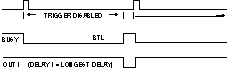
NIM level BUSY outputs are also provided by the 4222. Busy goes "true" in
response to a Trigger and remains "true" until the end of the shortest or
longest delay is selected by an internal switch.
Three outputs are provided for each channel. One output provides NIM-level signals which
go "True" after the programmed time delay and is reset by the Clear. Another
output gives complementary NIM logic output. Each channel has a corresponding delayed
pulse output that provides a 5 V fast rise time signal into 50 W occurring after the
programmed time delay.
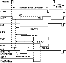
MODEL 4222 Trigger Timing Diagrams
Non-Retrigger Mode (Retrigger Action Switch: set to retrigger
disable) Diagram
Retrigger Before End of Delay (Retrigger Action
Switches: set to retrigger enable retrigger before end)
Retrigger After End of Delay (Retrigger Action Switches:
set to retrigger enable retrigger after end)
The Model 4222 may be set to retrigger mode permitting the unit to retrigger without being
reloaded by a side -panel switch. In Retrigger Mode, two options are possible, before or
after the delay period. The unit may be retriggered at any time (> 100 nsec after the
last trigger) or any time after the longest delay has elapsed.
Synchronization of many 4222 Gate and Delay Generators is possible. An external clock may
be used to feed several 4222 modules with an identical time base. Stability and accuracy
are then determined by the external clock.
INPUT
START: Bridged high impedance pair. Lemo-type connectors. Input trigger level
adjustable over the range �3 V via front-panel potentiometer, supplied at -400 �50 mV
with a negative-going edge. This input initiates the timing cycle.
STOP: Standard NIM input, Lemo-type connectors. This input terminates the timing
cycle in the latched mode. Active in both latched and preset modes. The delay is < 20
nsec.
OR: Standard NIM input, Lemo-type connector. Input impedance 50 ohm. Produces
outputs as long as the OR signal is asserted.
BLANK: Standard NIM input, Lemo-type connector. Input impedance 50 ohm. Cancels
gate outputs as long as the BLANK signal is asserted. Overrides OR input.
OUTPUT
BUSY LED: Indicates unit is active.
NIM: Standard NIM (-16 mA) signal, Lemo-type connector. Goes low for gate duration.
Rise time 2 nsec; fall time 2.5 nsec.
NIM*: Standard NIM (-16 mA) signal, Lemo-type connector. Goes high for gate
duration. Rise time 2 nsec; fall time 2.5 nsec.
ECL: Complementary ECL levels, 2-pin connector. PC-mounted shorting plug allows
this output to be logically identical to the GATE or DELAY pulse or their complements.
TTL: An FET open drain output (250 mA, 0.5 W maximum). PC-mounted shorting plug
allows this output to be logically identical to the GATE or DELAY pulse or their
complements.
DELAY: Standard NIM (-16 mA) signal, Lemo-type connector. Delayed from start of NIM
by the gate width. (Goes low at trailing edge of gate.) Programmable for 10, 30, 100 or
300 nsec duration. Rise time 2 nsec.
GATE WIDTH
Range: 100 nsec to 10 sec (50 nsec width at reduced accuracy and stability).
Accuracy: �0.2% of full scale.
Temperature Stability: < 200 ppm/�C.
Jitter: < 0.3% of setting.
Resolution: 0.1% of full scale.
DELAY WIDTH
Width Options: 10 nsec, 30 nsec, 100 nsec, 300 nsec.
Accuracy: �20%.
GENERAL
Input-Output Delay: 24 nsec (Start input to NIM output).
Recovery Time: None. The unit may be retriggered any time after the timing cycle
has been completed.
Packaging: Double-width module in conformance with CAMAC Standard; ESONE Report
EUR4100 or IEEE Report #583. RF-shielded.
Power Requirements: 1.8 A at +6 V; 1.3 A at -6 V; 50 mA at +24 V; 75 mA at -24 V;
21.6 W total.
INPUT
Trigger Input (TRIG): Two bridged front-panel Lemo-type connectors; high input
impedance, positive/negative edge selection via side-cover switch; threshold level
adjustable between -1.5 V and +1.5 V with a front-panel potentiometer; 10X threshold
monitor on front panel; minimum input width is 5 nsec; unused input must be terminated in
50 ohm.
Clear Input (CLR): Two bridged front-panel Lemo-type connectors; high input
impedance accepts NIM level pulses; minimum input width is 50 nsec; unused input must be
terminated in 50 ohm.
Clock Input (CK): Two bridged front-panel Lemo-type connectors; high input
impedance, selected by internal strap; NIM level inputs; unused input must be terminated
in 50 ohm. Clock input frequency must be 31.25 MHz
�0.1%. Stability determines the long-term accuracy of the time delays.
OUTPUT
BUSY and BUSY* Outputs (B & B*): Two front-panel Lemo-type connectors; NIM level
outputs. BUSY output state goes true in response to a valid Trigger and remains true until
either the end of the shortest delay or the end of the longest delay as selected by an
internal switch.
Delayed Level Outputs (OUT & OUT*): Two front-panel Lemo-type connectors per
channel; NIM level outputs; both direct (OUT) and complementary (OUT) outputs are
provided. A set of side-panel switches permits the selection of either independent outputs
or coupled window outputs:
­p; INDEPENDENT: 1, 2, 3, and 4: Each channel output (OUT) goes "true"
when the corresponding programmed time delay has elapsed; output is reset by the Clear or
by the next Trigger if the Retrigger Mode has been selected.
­p; COUPLED: 1 and 2, or 3 and 4: Channel 1 (3) output (OUT) goes "true"
when time delay 1 (3) has elapsed and goes "false" when time delay 2 (4) has
elapsed; delay 1 (3) < delay 2 (4). Channel 2 (4) output (OUT*) goes "true"
when delay 2 (4) has elapsed and is reset by Clear or by the next Trigger if the Retrigger
Mode has been selected.
Delayed Pulse Output (P1-P4): One front-panel Lemo-type connector per channel. Each
channel's PULSE OUT delivers a 1 nsec rise time 5 V pulse (into 50 ohm) when the
corresponding time delay has elapsed; pulse width 100 nsec �10%.
GENERAL
Delay Range: 170 nsec to 16.777215 msec in 1 nsec increments.
Accuracy: �200 psec � time base error.
Jitter: 150 psec R.M.S. maximum; up to 1 msec delay (see manual for additional
information).
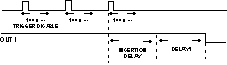
Insertion Delay: 170 nsec.
Crosstalk: < 500 psec when delays differ by less than 8 nsec, 0 otherwise.
Internal Time Base: High stability quartz oscillator:
f/f0 : �5 � 10^-6 initial frequency tolerance;
Tc : < 0.5 ppm/�C;
Aging : < 3 � 10^-9/day.
Packaging: Single-width standard CAMAC module.
Power Requirements: 40 mA at +24 V; 1.3 A at +6 V; 2.5 A at -6 V; 130 mA at -24 V.
Model 2323A Dual Programmable Gate and Delay Generator
CAMAC COMMANDS
C or Z: Stops channels A and B gates.
X: X response is generated for each valid function.
Q: Q response is generated for each valid function unless otherwise specified.
CAMAC FUNCTION CODES
F(1)�A(0): Read channel A programming word.
F(1)�A(1): Read channel B programming word.
F(9)�A(0): Stop channel A gate.
F(9)�A(1): Stop channel B gate.
F(17)�A(0): Write channel A programming word.
F(17)�A(1): Write channel B programming word.
F(25)�A(0): Start channel A gate.
F(25)�A(1): Start channel B gate.
CAMAC COMMANDS
Z: Initializes module, resets all channels, disables trigger input and enables CAMAC
access (does not reset data registers).
C: Resets all channels (does not reset data registers) equivalent to front-panel
Clear input.
I: Disables trigger input when present.
X: X response is generated for each valid function.
Q: Q response is generated for each valid function unless otherwise specified.
CAMAC FUNCTION CODES
F(0)�A(0-3): Reads selected program delay for channels 1-4 in 24 bits; Q = 1 always;
24-bit unsigned integer convention.
F(1)�A(0): Reads status via READ lines 1-4: R1 = 1 if shortest delay elapsed; R2 =
1 if longest delay elapsed; R3 = 1 if Model 4222 is ready for trigger; R4 = 1 if CAMAC
access enabled. All states are strobed by the leading edge of the CAMAC N signal.
F(9)�A(0): Resets all channels (does not reset data registers) equivalent to
external Clear input.
F(16)�A(0-3): If CAMAC access enabled, writes delay to selected channel 1-4 in 24
bits. Q = 1 if CAMAC access enabled; Q = 0 otherwise. 24-bit unsigned integer convention.
F(24)�A(0): Disables unit; enables CAMAC access.
F(25)�A(0): Triggers the unit (OR'd with the external front-panel Trigger input):
Q = 1 if unit was ready for trigger; Q = 0 otherwise.
F(26)�A(0): Enables unit; disables CAMAC access.
Copyright� September 1995. LeCroy is a registered trademark of LeCroy Corporation.
All rights reserved. Information in this publicaction supersedes all earlier versions.