Key Features
-
Automatic switching device measurements
-
Color coded overlay to identify power losses
-
Control loop and time domain response analysis
-
Line power and harmonics tests to IEC 61000-3-2
-
Setup tools reduce sources of measurement error
-
Total harmonic distortion table shows frequency contribution
-
B-H Curve shows magnetic device saturation
Quickly Measure and Analyze Operating Characteristics of Power Conversion Circuits
Critical power switching device measurements, control loop modulation analysis, and line power harmonic testing are all simplified with a dedicated user interface and automatic measurements. Power Analysis provides quick and easy setup of voltage and current inputs and makes measurements as simple as the push of a button. Tools are provided to help reduce sources of measurement errors, measurement parameters provide details of single cycle or average value over multiple cycles.
Automatic Switching Device Measurements
Areas of power device turn-on and turnoff transitions, and conduction are all identified with color-coded waveform overlays. Measurement parameter table automatically calculates each element of device losses and sums their total.
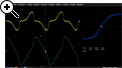
Control Loop Response Analysis
Modulation analysis capabilities provide insight to understand control loop response to critical events such as a power supply’s soft start performance or step response to line and load changes.
Line Power and Harmonics Testing
Line power analysis tools provide insight to power consumption as well as enables quick precompliance testing to EN 61000-3-2. Decisions on power quality are aided with total harmonic distortion and analysis of contributions to distortion.
Support on Multiple Oscilloscope Platforms
The Power Analysis Package is available on a wide range of oscilloscope models from 200 MHz to 65 GHz.
Power device analysis
Analyze power device performance while the device is operating in circuit. Easily make switching loss, dynamic-on resistance, dv/dt and di/dt measurements. Quickly view safe operating area and B-H hysteresis curves.
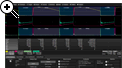
Power Device Losses
Turn-on, turn-off and conduction zones are identified with a colorcoded overlay, power losses in these zones are automatically measured and displayed. Losses associated with the switching, conduction, and off-state are measured independently and displayed along with the sum of selected loss types.
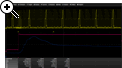
Safe Operating Area
Gain insight to circuit performance by seeing SOA plots to look for violations in the first cycles after an event or over long time periods. Finding SOA violations that occur for only a few cycles after an event, such as short circuit or startup, can be problematic. These violations often go undetected, and degrade the device over time.
Using the long record length and fast processing of Power Analysis, SOA display on very long records, confirm turn-off voltage and current limits are not exceeded.
B-H Hysteresis Curve
View the behavior of a magnetic device while it operates in circuit. Dynamic circuit changes show resulting magnetic saturation and operating region.
Control Loop Analysis
View time domain display which graphically presents the modulated parameter in a time vs. parameter value graphical plot. A controller’s output pulse widths, duty cycles or frequencies, are individually plotted and time correlated with the controller’s output. Integrated with the oscilloscope’s triggering capabilities, this analysis is a convenient tool for intuitively viewing the time domain, closed-loop response of the entire control loop, including any time constants added by the pulse width modulator.
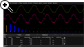
Line Power Analysis
Easily measure an off-line power supply’s incoming RMS line voltage, RMS current consumption (in watts and VA), Power Factor, Apparent Power, Real Power and Crest Factor. Line current harmonic measurements are made and compared to standard templates for EN 61000-3-2 Class A, B, C, or D equipment. Results can be displayed graphically to see mask violations or in a table with test results. Total harmonic distortion measurements are provided with details of which frequencies are contributing to the distortion.