Key Features
-
DDR3 test coverage as described by JESD79-3F
-
DDR3L test coverage as described by JESD79-3-1A
-
LPDDR3 test coverage as described by JESD209-3B
-
Test speeds up to 2133 MT/s
-
Perform automated compliance of JEDEC electrical requirements
-
Measurement repeatability, consistency and accuracy
-
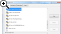
Save Pass/Fail reports with annotated screenshots
-
Analyze compliance failures in a dedicated Debug Toolkit
-
Included in DDR5 Software Bundle
DDR5 Software Bundle
The best tools cover all stages of design, from early turn-on through compliance. This means planning for the future, it might be testing DDR3 to DDR4 or upgrading to DDR5 designs. The DDR5 Bundle includes all the best tools (DDR Debug Toolkit + QualiPHY) across all generations, in a single purchasable software bundle.
QualiPHY
QualiPHY is designed to reduce the time, effort, and specialized knowledge needed to perform compliance testing on high-speed serial buses.
-
Guides the user through each test setup
-
Performs each measurement in accordance with the relevant test procedure
-
Compares each measured value with the applicable specification limits
-
Fully documents all results
-
QualiPHY helps the user perform testing the right way—every time!