In-vehicle Network Testing (CAN bus, Automotive Ethernet and other Vehicle Bus Networks)

Classic and Domain ArchitectureClassic and Domain Architecture
Automotive EthernetAutomotive Ethernet
InfotainmentInfotainment
Next Generation E/ENext Generation E/E
OscilloscopesOscilloscopes
Cable TestingCable Testing
ResourcesResources

More Capability for Vehicle Bus Network Test

Teledyne LeCroy has a rich history in vehicle bus network test and supports more vehicle standards and more tests in a much more rigorous way than any other oscilloscope vendor.

  • Comprehensive support from kb/s to Gb/s
  • The most capable and versatile oscilloscopes
  • The most effective tools to assess cable quality

Teledyne LeCroy - The Innovators for In-vehicle Network Testing

Teledyne LeCroy’s first digital oscilloscopes made possible the modern era of electronic control of all aspects of vehicle operation. Our rich history of innovation in this market and our extensive range of equipment provides the comprehensive solutions you need from kb/s to Gb/s.

Vehicle wireframe drawing showing IVN ECUs connected vehicle bus networks in a vehicle network architecture

Comprehensive from kb/s to Gb/s, Debug to Compliance

  • Most sophisticated tools for classic and domain architecture debug
  • Most comprehensive automotive ethernet solutions from 10 Mb/s to 10 Gb/s
  • Complete infotainment and next-generation zonal E/E architecture test
Oscilloscope and other test equipment used for in-vehicle network test for CAN bus, automotive IVI, MIPI DSI, MIPI CSI, MIPI DPHY, MIPI APHY, ASA ML and MLE and various other vehicle network protocols

Most Capable and Versatile Oscilloscope Platforms

  • Every IVN standard on every oscilloscope –200 MHz to 65 GHz
  • 12-bit resolution all the time for unmatched measurement precision
  • Powerful standard toolbox and application packages
In vehicle network cable assemblies used for various vehicle communication networks and protocols

Most Effective Tools to Assess Cable Quality

  • Frequency-domain network analyzers for debug and understanding
  • Time-domain TDRs to assess cable asymmetry
  • Compliance test packages for new designs

Comprehensive In-vehicle Network Test Tools from kb/s to Gb/s, Debug Through Compliance

Various vehicle bus protocols are used to meet specific communication speed, safety, and cost requirements. Different test toolsets are needed to evaluate these bus systems and quickly detect faults during development.

Most Sophisticated Tools for Classic and Domain Architecture Debug

Ubiquitous low-speed technologies like Controlled Area Network (CAN), J1939, Local Interconnect Network (LIN), Manchester encoding, SENT, and PSI5 benefit from sophisticated tools that speed debug and reduce development time.

  • Powerful and unique triggers and decoders for faster debug and validation efficiency
  • Quickly validate cause and effect with automated timing measurements and unique graphing tools
  • Use eye diagrams to quantify system performance and debug signal integrity issues

Most Comprehensive Auto Ethernet Test Solutions from 10 Mb/s to 10 Gb/s

Automotive Ethernet provides a single universal communication medium that allows different components to coexist in the same switched network. Teledyne LeCroy’s automotive ethernet test solutions further the evolution of the vehicle into a mobile data center.

  • Best 10Base-T1S and Open Alliance 3-pin interface (OA3p) tools for PLCA analysis and for identifying physical layer issues
  • Dedicated 100Base-T1 and 1000Base-T1 debug environment with the only in-circuit signal equalization tools for accurate signal validation and decode

Complete Infotainment and Next-generation Zonal E/E Architecture Test

Zonal architectures enable advanced drvier assistance (ADAS), autonomous driving, and much more complex infotainment capabilities than are currently possible with domain architectures. Teledyne LeCroy’s high-speed serial data and DDR test capabilities make us uniquely positioned in the test marketplace.

  • Strong presence in computing industry standard-setting bodies (e.g., PCI-SIG®, USB-IF, ASA), whose technologies are being adopted into vehicles.
  • Oscilloscope (up to 65GHz) and Protocol Analyzers for all relevant technology standards
  • DDR
  • PCI®
  • USB, HDMI® and DisplayPort™
  • Automotive SerDes Alliance (ASA)
  • MIPI
  • Bluetooth®
  • Serial data jitter and eye diagram analysis for all non-standardized interfaces

Classic and Domain Architecture In-vehicle Network Testing

Get faster debug using the most sophisticated test tools when testing ubiquitous low-speed vehicle bus network protocols, such as Controlled Area Network (CAN), J1939, Local Interconnect Network (LIN), Manchester-encoded signaling, SENT, and PSI5.

CAN FD vehicle network protocol signal acquisition, color-coded decode overlay and table and eye diagram showing signal infringement on eye mask
LIN vehicle network protocol signal acquisition with color-coded decode overlay and table
FlexRay vehicle network protocol signal acquisition with color-coded decode overlay and table and eye diagram showing infringement of signal onto eye mask
SENT vehicle network protocol signal acquisition with color-coded decode overlay and table and plots of SENT digital data extracted and converted to an analog waveform.
Manchester-encoded in-vehicle network signal acquisition (e.g. PSI5 vehicle network protocol) with color-coded decode overlay and table

Teledyne LeCroy’s CAN, CAN FD and CAN XL options support use of a customer-supplied DBC or ARXML file for symbolic trigger signal selection and decode of complete message and signal structures. Conversion of CAN digital messages to analog, scaled values (serial data DAC) is also provided.

Teledyne LeCroy’s LIN trigger, decode and measurement toolsets permit isolation of specific bit-level data patterns in one or more data bytes, e.g., data location in bits 18-26 spanning data bytes 2 and 3. This provides significant advantages in isolating the exact information or behavior you need.

Teledyne LeCroy simplifies the analysis of the complex FlexRay protocol. Powerful physical layer test analysis functions are provided, SI voting is supported, and important timing parameters, such as propagation delay, asymmetric delay, truncation, and jitter provide detailed information on how signals propagate along the channel.

Teledyne LeCroy supports analysis of both fast and slow SENT channels and independent definition of the nibbles and offset for each data word. The unique column-to-value parameter helps to check the stability of the MTP over time and correlate the sensor activity with other signals in the system.

Teledyne LeCroy’s configurable Manchester decode option enables flexible, user-definable protocol decoding of serial buses such as PSI5. Physical layer specifications (e.g., bit rate, idle state, polarity) are easily defined for decoding of every bit transmitted on the bus. Higher level decode can be done by configuring bits to words and then words to packets.

The Widest Range of CAN Bus Test Solutions with the Most Power and Flexibility

Support for Classic CAN, CAN FD, CAN FD Light, and CAN XL on oscilloscopes from 200 MHz to 65 GHz, with more capability to find problems faster.

More CAN Bus Test Capability Than Any Other Vendor

Teledyne LeCroy offers the industry's most comprehensive set of CAN bus debugging tools, including advanced trigger, decoder, measurement, graphing, and the first true CAN eye diagram for arbitration or data – all fully symbolic capable.

  • Supports all CAN versions: Classic CAN, CAN FD, CAN FD Light and CAN XL up to 20 Mbit/s
  • True CAN eye diagram with mask testing on Arbitration or Data with filterable IDs
  • Automated timing measurements
  • Serial data digital-to-analog value conversion (DAC) with correct units
  • Symbolic (.ARXML and .dbc) trigger, decode and analysis capability

Supports all Versions of CAN and CAN Protocol Variants

Teledyne LeCroy supports all versions of CAN, including the latest CAN FD Light and many protocol variants.

  • Supports Classic CAN and CAN FD
  • Supports CAN XL SIC and CAN XL FAST mode with bitrates up to 20 Mbit/s
  • Supports new CAN FD Light standard with extended trigger on bitrates up to 8 Mbit/s
  • Supports many CAN protocol variants such as GM LAN, J1939, J1939+1, J1939+2

True CAN Eye Diagrams Evaluate Signal Integrity as Seen by a Real CAN Receiver

Teledyne LeCroy Eye diagram clock recovery, emulates the behavior of a real CAN receiver and provides the only accurate bit-sliced view of the physical layer CAN signal as it exists in your circuit

  • Quick, intuitive assessment of in-circuit CAN signal quality
  • Eye diagrams can be generated for both arbitration and data, with or without masks
  • Filter the data for IDs to quickly isolate signal integrity problems in the CAN network to a single CAN transmitter
  • Watch Webinar about CAN Eye diagrams

Serial Data Digital-to-Analog CAN Value Conversion with Correct Units

Extract digital serial data and convert it to a scaled and unitized analog value. Then display it as a value vs. time waveform – it’s a serial data DAC.

  • Intuitive and simple view to monitor system performance
  • Select a specific message for DAC using Symbolic .ARXML or .dbc files
  • Create time-correlated value vs. time waveforms
  • Convert units to over 70 different units of measure

Automated CAN Timing Measurements

Quickly validate cause and effect with automated timing measurements between a CAN message and to or from an analog signal or between CAN or other serial data messages.

  • Unique automated timing and bus measurements to speed debug and validation.
  • Measure gateway performance by measuring timing between any two serial data messages.
  • Make multiple measurements in a single long acquisition to quickly acquire statistics during corner-case testing

Symbolic (.ARXML and .dbc) Setup and Analysis Capability

CAN trigger, decode and measure/graph options support use of a customer-supplied DBC or ARXML file for signal selection for triggering and CAN to Value serial data DAC setup. Additionally, the decode annotation is in Symbolic format as well, with complete message and signal structures described.

  • Simply select a CAN message and signal in the .ARXML or .dbc database and define the data range to trigger the oscilloscope.
  • Decode data presented in symbolic form in the results table.
  • Simplifies setup of digital-to-analog conversion of CAN message data into analog rescaled and unitized values for simple understanding of embedded digital data.
  • Watch Webinar

10Base-T1S Automotive Ethernet

Teledyne LeCroy offers industry-leading 10Base-T1S tools for PLCA analysis, physical layer diagnostics, and comprehensive OA3p interface debugging between MAC and PHY

More Efficient Troubleshooting and Analysis

Unique trigger/decode, measure/graph and eye diagram (TDME) features provide faster debug and more efficient troubleshooting.

  • Comprehensive and powerful triggering on Beacon, ID, ID + DATA, Commit/Sync, ESD and CRC-Error
  • Measure/Graph tools automate many measurements for validation efficiency
  • Verify PLCA timing with automated measurements
  • Eye diagram displays can be filtered by node ID
  • Eye diagram failure location identifies root-cause physical layer issues

Comprehensive and Powerful 10Base-T1S Trigger

Teledyne LeCroy 10Base-T1S is the only oscilloscope trigger for 10Base-T1S automotive ethernet and single-pair ethernet.

  • Simplified trigger (and decoder) setup through automatic assignment of node ID to MAC address based on analysis of the PLCA cycle.
  • Conditional trigger setup for the DATA condition — especially useful for detecting abnormal events, such as when a node broadcasts a low or high engine RPM or coolant pressure.

Comprehensive OA3p interface debugging between MAC and PHY

The OPEN Alliance 3-pin (OA3p) interface is an enhanced physical layer standard designed to simplify Ethernet connectivity in automotive systems, particularly for 10BASE-T1S networks. Gain deeper insights with unique OA3p trigger and decode capabilities.

  • Trigger and decode OA3p traffic to check config, status, and data integrity
  • Decode and inspect received data to detect interference or signal integrity issues on the MDI interface
  • Verify transceiver configuration by monitoring decoded MDIO commands and traffic.

Verify PLCA Timing with Automated Measurements

Get more insight by automatically measuring the beacon-to-beacon timing during a long acquisition.

  • View the results as data in a measurement table, showing mean, minimum, maximum and other results.
  • Display the results as a waveform of measured beacon-to-beacon time values versus time, time-correlated to the original acquisition waveform.
  • Observe the statistical distribution of the complete set of beacon-to-beacon time values as a data histogram.

Measure/Graph Tools Provide Higher Validation Efficiency

Unique automated timing and bus measurements and a software serial data digital-to-analog converter (DAC) to speed debug and validation.

  • Quickly validate cause and effect from an analog signal or another serial message to understand PLCA timing issues.
  • Measure gateway performance by measuring timing between any two serial data messages.
  • Make multiple measurements in a single long acquisition to quickly acquire statistics during corner-case testing.
  • Extract digital serial data and convert to a scaled and unitized analog value and show it as a value vs. time waveform to simplify monitoring of system performance.

Filtered Eye Diagrams Quickly Identify Physical Layer Issues

Eye diagram displays of bit transmissions with filtering and masks help to resolve issues quickly.

  • Filter decoded data by specific node IDs prior to displaying in the eye diagram to identify PLCA cycle issues.
  • Eye diagram parameters quantify system performance
  • Apply a custom mask to isolate and identify anomalies.
  • Display mask violation errors and STOP the oscilloscope acquisition after an error violation.

100Base-T1 and 1000Base-T1 Automotive Ethernet

Teledyne LeCroy has a dedicated debug environment with integrated equalization for 100Base-T1 and 1000Base-T1 automotive ethernet debug.

Integrated Equalization for Real-world Signal Acquisition and Debug

Teledyne LeCroy is the only oscilloscope vendor to provide an integrated equalizer that shows actual device-under-test receiver behavior and improves decoding of acquired signals.

  • Enhanced signal separation, receiver equalization and decode
  • Analyzes startup phase and data traffic for fastest debugging
  • Quickly assess signal integrity and characterize/quantify performance using PAM3 eye diagrams

Only Integrated Oscilloscope Receiver Equalization for 100Base-T1 and 1000Base-T1

A single tool connects the entire signal processing flow, from input through equalizer functions to the final output to the eye diagram display and/or decoder.

  • Provides the only accurate and reliable assessment of system performance
  • Eliminates erroneous, confusing and contradictory signal, protocol, and eye diagram views
  • Ensures that decoding is operating on a signal unaffected by the test fixture

Unique Enhanced Signal Separation Using Bi-directional Coupler

Teledyne LeCroy’s TF-AUTO-ENET test fixture and software provide reproduction of real-world conditions and also superior signal fidelity compared to other directional coupler approaches.

  • Separate bi-directional link traffic to independently view signals from the Master and Slave.
  • Correctly compensates for the effects of the bi-directional coupler.
  • Integrated receiver equalization works with the bi-directional coupler and provides separate equalizer parameter settings for the Master and Slave to more accurately eliminate attenuation impacts.

Analyze Startup Phase and Data Traffic for Fastest Debugging

Trigger on and decode the link startup handshaking between the Master and Slave. Track where the devices are in the handshaking sequence to determine the cause of a proper link not being established.

  • Trigger on and decode the link startup handshaking between the Master and Slave.
  • Track where the devices are in the handshaking sequence to determine the cause of a proper link not being established.

Quickly Assess Signal Integrity of PAM3 Signals

PAM3 eye diagrams provide an intuitive and simple view of 100Base-T1 and 1000Base-T1 PAM3 signals.

  • Analyze signal quality communication problems between the master and the slave that are not identifiable during compliance testing.
  • Fully characterize and quantify link performance using 12 different eye measurement parameters.
  • Measure both upper and lower eye performance simultaneously
  • View system failure rates with customizable adjustable bit error rate (BER) contours in addition to captured eye diagram data.

Automotive Ethernet and Single Pair Ethernet (SPE) Compliance Testing

Teledyne LeCroy provides comprehensive compliance testing for 10Base-T1S, 10Base-T1L, 100Base-T1, 1000Base-T1 and MultiGBase-T1, including both Physical Media Attachment (PMA) and TC8 specifications, MDI return loss and Link testing.

10 base t1s, 100 base t1, 1000 base t1 and multi gbase t1 automotive ethernet compliance test equipment for PHY (electrical), PMA, TC8 specification, and MDI return loss testing
Automotive ethernet compliance test connection diagram demonstrating that neither MATLAB or a frequency divider is needed to perform measurements using Teledyne LeCroy oscilloscopes and other equipment.
Automotive ethernet compliance test equipment for PHY (electrical) for TC8 and IEEE 802.3cg, IEEE 802.3bw, IEEE 802.3bp, and IEEE 802.3cg specifications
MDI Return loss and MDI Mode Conversion using T3SP15D True Differential Time Domain Reflectometer
MDI, Cable and Connector measurement using WavePulster40iX interconnect analyzer
Teledyne LeCroy provides all necessary high-performance test fixtures for use with H-MTD®, MATEnet and Mini50 connectors.

Teledyne LeCroy provides full compliance test support for all Automotive Ethernet and Single Pair Ethernet (SPE) standards from 10 Mb/s to 10 Gb/s and for transmitter, MDI and Link.

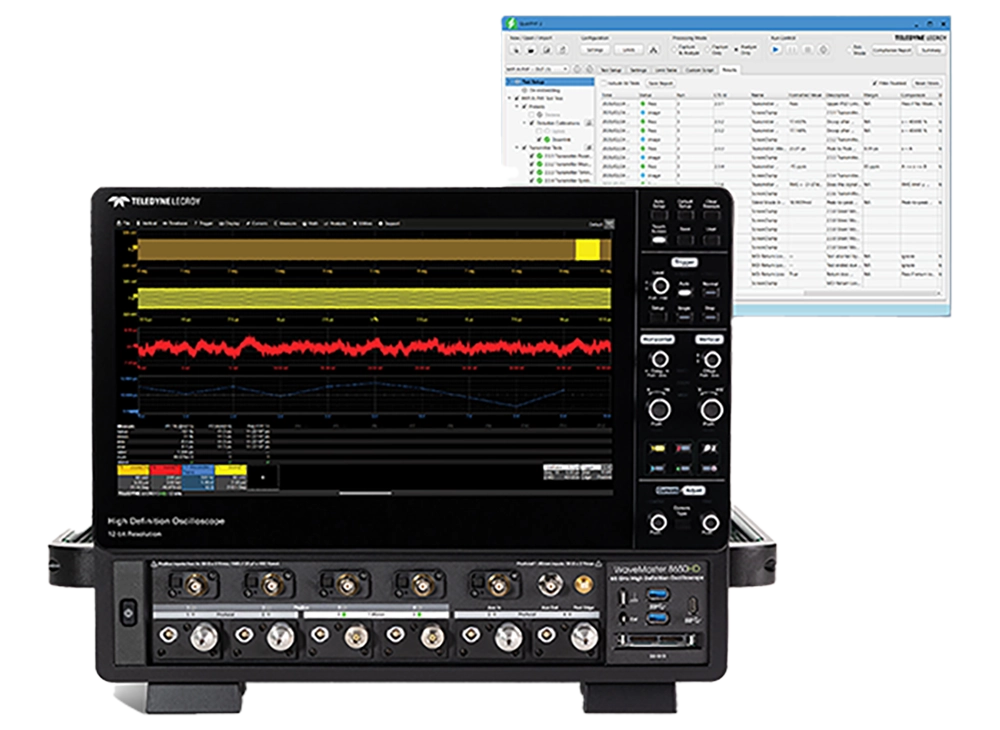
The QualiPHY 2 automated compliance test framework is elegantly implemented and complete. Testing is simple - everything is built in and there is no need for additional third-party software or hardware.

  • One vendor (Teledyne LeCroy) provides everything required, increasing test confidence and reliability.
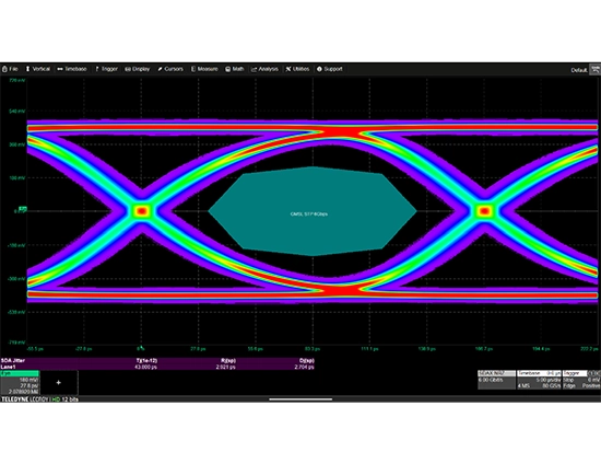
  • Software clock recovery is performed for the distortion test, simplifying setup and increasing reliability.
  • Tests can be performed faster and with more confidence.

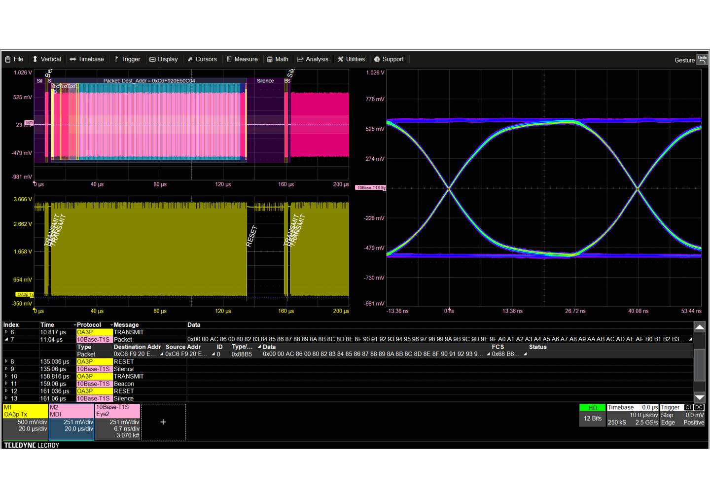
QualiPHY 2 test framework has a simple interface, guided instructions, and automated measurement engine to make complex transmitter tests easy to run, repeat, and document—ensuring efficient, reliable performance in every test session.

  • Support for all TC8 Specification Physical Media Attachment (PMA) and Transmitter tests
  • It guides the user through the connection and execution of each test, resulting in increased repeatability
  • Each measurement is performed in accordance with the relevant test procedure and compared and documented against the specification limits

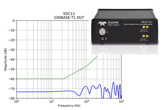
Teledyne LeCroy provides accurate and simple MDI return loss and mode conversion measurements for automotive ethernet and Single Pair Ethernet.

  • Support for 10Base-T1S, 10Base-T1L (IEEE 802.3cg), 100Base-T1 (IEEE 802.3bw), 1000Base-T1 (IEEE 802.3bp), and MultiGBase-T1 (IEEE 802.3ch) at 2.5, 5 and 10 Gb/s.
  • Innovative mode-conversion method dramatically increases dynamic range by reducing instrument-related error.
  • Reduced test time by reusing raw TDR data across multiple standards—no recalibration needed when changing frequency ranges.
  • QualiPHY 2 automated compliance test framework unifies all required Transmitter, MDI and Link tests into one test framework.

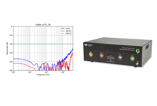
Comprehensive link (MDI, channel, cable and connector) time and frequency domain characterization for Single Pair Ethernet and Automotive Ethernet. including impedance, delay, insertion loss, return loss, and mode conversion parameters defined in IEEE802.3 and Open Alliance TC9.

  • Support for 10Base-T1S, 10Base-T1L (IEEE 802.3cg), 100Base-T1 (IEEE 802.3bw), 1000Base-T1 (IEEE 802.3bp), and MultiGBase-T1 (IEEE 802.3ch) at 2.5, 5 and 10 Gb/s.
  • Supports all MDI tests and capabilities as described in previous MDI Tests tab
  • Includes impedance, delay, insertion loss, return loss, and mode conversion parameters defined in IEEE802.3 and Open Alliance TC9.
  • WavePulser 40iX provides VNA-grade S-parameter accuracy with TDR-based spatial resolution for superior performance.
  • QualiPHY 2 automated compliance test framework unifies all required Transmitter, MDI and Link tests into one test framework

Teledyne LeCroy provides all necessary high-performance test fixtures for use with H-MTD®, MATEnet and Mini50 connectors.

  • Support for Rosenberger H-MTD high-speed modular twisted-pair data connector (Teledyne LeCroy TF-AUTO-HMTD test fixture)
  • Support for TE Connectivity MATEnet miniaturized automotive ethernet connector system (Teledyne LeCroy TF-AUTO-MATENET test fixture)
  • Support for Molex Mini50 connectors (TF-AUTO-MINI50)
  • High-quality 3.5 mm connectors (compatible with SMA) used throughout
  • >2.5 GHz bandwidth (TF-AUTO-MATENET, TF-AUTO-MINI50)
  • >13 GHz bandwidth (TF-AUTO-HMTD)

Complete In-Vehicle Infotainment (IVI) Test Support

Teledyne LeCroy can meet your needs for testing for In-vehicle Infotainment (IVI) and In-car Infotainment systems that use MIPI CSI/DSI, Bluetooth, USB, DisplayPort, MOST-bus, or a proprietary LVDS or SerDes signal.

Automotive IVI infotainment signal testing using Teledyne LeCroy oscilloscope and Anritsu MP1900A Signal Quality Analyzer (BERT)
MIPI C-PHY signal acquisitions with measurements and an eye diagram display, similar to what could be made for MIPI DSI, MIPI CSI, MIPI D-PHY or MIPI M-PHY
Screen capture of usb analysis software
MOST signal eye diagram display on a Teledyne LeCroy scope
LVDS or SerDes serial data and jitter analysis with eye diagram and jitter measurements

Complete PHY and PHY-logic layer oscilloscope solutions for USB4®, Thunderbolt™, USB 3.0/2.0, DisplayPort™ 2.1, and USB Power Delivery, all over the USB Type-C Connector.

  • The best oscilloscope for USB-C testing
  • Built-In USB-C test expertise for measuring and characterizing signals
  • Simplify USB-C link testing with cross layer analysis

Teledyne LeCroy’s decode and physical layer test solutions for MIPI M-PHY, C-PHY and D-PHY are the ideal tool for powerful system-level protocol debugging and troubleshooting of signal quality issues.

Gigabit Multimedia Serial Link (GMSL) is a widely used asymmetric full-duplex SerDes technology. This means that it transports data at a high rate in the downlink (or forward) direction, while at the same time transmitting a lower data rate in the uplink (or reverse) direction.

  • Teledyne LeCroy SDA Expert test software operates on high-resolution 12-bit oscilloscopes (HDO®)
  • Includes all the settings to perform a mask test compliant with the GMSL2 specification.
  • Any detected failures can be debugged with SDA Expert tool kits
  • Explore More about SDA Expert

Teledyne LeCroy created the first physical layer compliance test package for MOST® Bus (Media-Oriented Systems Transport) and supports all current MOST electrical and optical standards.

LVDS and various Serializers/de-serializers (SerDes) are used to transmit fast signals, such as camera signals, over longer lines. Teledyne LeCroy SDA Expert serial data analysis software option tests these proprietary interfaces.

  • Most complete toolbox for analyzing any serial data signal
  • Highest confidence for complex measurements
  • Unique Multi-view support with reference and comparison modes
  • Built-In Report Generator

Support For Next-generation Automotive E/E Architectures

Teledyne LeCroy offers the test solutions for electrical/electronic (E/E) architectures that are likely to become critically important as vehicles evolve to zonal architectures and mobile computing centers.

Oscilloscope testing application for pcie automotive test, such as might be used in next-generation vehicle network architecture
Oscilloscope testing DDR signals that might be used in a used in next-generation zonal vehicle network architecture
ASA ML acquired signal with eye diagram, pulse response and SNDR analysis.
mipi a-phy
LVDS or SerDes serial data and jitter analysis with eye diagram and jitter measurements

Teledyne LeCroy is the only company that provides PCI Express® (PCIe) testing across the layers – protocol to physical – while also providing superior instruments with sophisticated jitter, eye diagram, debug and compliance software.

  • Approved PCIe, CXL, and NVMe base and compliance test solutions
  • Most confidence for PCIe compliance and interoperability testing
  • Simplified PCIe link testing with cross-layer analysis
  • Built-in PCIe expertise for measuring and characterizing signals

Accelerate the journey to final product with the right tools to quickly test every stage of Double Data Rate (DDR) and Low Power DDR (LPDDR) designs, from initial turn on through JEDEC compliance testing.

  • Maximize DDR operation from initial turn-on through validation
  • Accelerate DDR pre-compliance testing and fine tuning
  • Comprehensive DDR compliance testing
  • Probe solutions available for automotive temperature range

ASA Motion Link defines an asymmetric SerDes communication technology for in-vehicle connectivity with line speeds from 2 Gbit/s to 16 Gbit/s - ideal for the transmission of data from cameras, displays and ADAS systems. Teledyne LeCroy’s first-to-market compliance test software and 12-bit high-definition oscilloscopes (HDO®) support needs for ASA multi-level signal testing.

  • Benefits from Teledyne LeCroy’s long-term involvement in ASA Automotive SerDes standards committees
  • Built with latest-generation QualiPHY® 2 compliance test framework
  • Any detected compliance failure can be debugged with SDA Expert tool kits
  • Test and validation on real ASA-compliant devices performed at ASA Plugfests
  • Explore More about QPHY2-ASA

MIPI A-PHY is an asymmetric data connection whose main task in the car is data transmission between cameras and displays and the associated control units for ADAS or IVI functions. With a range of up to 15 metres, higher-value protocols such as CSI-2 and DSI-2 can also be operated directly across vehicles via a physical connection.

  • Teledyne LeCroy's first-to-market compliance test software operates on high-resolution 12-bit oscilloscopes (HDO®)
  • Benefits from Teledyne LeCroy’s long-term involvement in MIPI Automotive SerDes standards committees
  • Built with latest-generation QualiPHY® 2 compliance test framework
  • Any detected compliance failure can be debugged with SDA Expert tool kits
  • Test and validation on real A-PHY-compliant devices performed at A-PHY Plugfests
  • Explore More about QPHY2-MIPI-APHY

Serializers/de-serializers (SerDes) are used to transmit fast signals, such as camera signals, over longer lines. Teledyne LeCroy SDA Expert serial data analysis software option tests these proprietary interfaces.

  • Most complete toolbox for analyzing any serial data signal
  • Highest confidence for complex measurements
  • Unique Multi-view support with reference and comparison modes
  • Built-In Report Generator

Most Capable and Versatile Oscilloscope Platforms

Teledyne LeCroy offers a wide variety of 8-bit or 12-bit digital oscilloscopes from 100 MHz to 65 GHz. Capture every detail with 12 bits of vertical resolution all the time and up to 8 Gpts of acquisition memory

teledyne lecroy oscilloscopes

Every IVN Standard on Every Oscilloscope, 200 MHz to 65 GHz

No other vendor offers such support over this range of oscilloscopes
hd4096 12 bit resolution

12-bit Resolution All the Time for Unmatched Measurement Precision

Once you use a Teledyne LeCroy HDO, you’ll never want to go back to using another oscilloscope.
  • Clean, Crisp Waveforms
  • More Signal Details
  • Unmatched Measurement Precision
teledyne lecroy periodic table of tools

Powerful Standard Toolbox and Application Packages

Teledyne LeCroy provides the most standard toolbox capability and many optional application packages

Most Effective Tools to Assess Cable Quality

Teledyne LeCroy has a range of network analyzers and time domain reflectometers (TDRs) to quickly and effectively test your designs and your supplier's products.

WavePulser 40iX High-speed Interconnect (Network) Analyzer

Unmatched characterization insight at a fraction of the price of a Vector Network Analyzer (VNA)

  • S-parameters DC to 40 GHz, single-ended and mixed-mode
  • Impedance Profile with <1 mm resolution, differential and common-mode
  • Internal, automatic OSLT calibration
  • USB-connected, small, lightweight

T3SP Time Domain Reflectometers

Stimulate the DUT with true differential signals and measure impedance profiles and S-parameters.

  • 1 GHz or 15 GHz models
  • Rise time as fast as 35 ps
  • True Differential and Single-ended TDR
  • Ultra portable and battery powered

Resources

Name

Automotive Ethernet Test Solutions

Automated compliance testing, debug toolkits, test fixtures and other solutions for testing automotive ethernet, from 10 Mb/s to 10 Gb/s.

Datasheet

Application Note - Next Generation Automotive Design (Japanese)

次世代自動車のデザイン

Application Note

GMSL Physical Layer Validation

GMSL2 is a standard for serial data transmissions used ADAS, autonomous driving and infotainment systems. This app note describes how to perform physical layer testing on GMSL2 signals.

Application Note

Serial Data Trigger Decode Datasheet

Trigger, decode, measure/graph and eye diagram test tools for CAN and CAN FD, LIN, FlexRay, 10Base-T1S, 100Base-T1, 1000Base-T1, SENT, Manchester/PSI-5 and various other low-speed serial data standards.

Datasheet

Decoding a SENT Protocol

Application Note

Product Line Card

Oscilloscope, Protocol and Digitizer Products Line Card

Datasheet

Teledyne LeCroy Mid- to High-bandwidth Oscilloscopes Options and Accessories Catalog

Description of standard oscilloscope features, options and accessories provided with or available for mid-bandwidth to high-bandwidth oscilloscopes.

Datasheet

Teledyne LeCroy Low-bandwidth Oscilloscopes Options and Accessories Catalog

Description of standard oscilloscope features, options and accessories provided with or available for low-bandwidth oscilloscopes.

Datasheet

Application Note – CAN Sensor Characterization

CAN-specific parameters measure sensor performance speed up validation of CAN/CAN FD ECU or network performance.

Application Note

Application Note – Smart CAN Triggering

Time and Event qualified CAN Triggers will greatly increase your ability to debug a CAN/CAN FD ECU or network.

Application Note

Application Note – Decoding a SENT Protocol

Review the basics of the SENT protocol and how to use a Teledyne LeCroy oscilloscope equipped with configurable SENT protocol decode software to properly decode SENT signals.

Application Note

Application Note – Decoding PSI5 with the Manchester Configurable Decoder

Learn how to use the Manchester configurable protocol decode software to properly decode PSI5 signals

Application Note

Application Note – Verifying the Stability of the SENT SPC MTP

This application note describes the SENT SPC protocol and demonstrates how to use a Teledyne LeCroy oscilloscope to verify a consistent Master Trigger Pulse (MTP) length.

Application Note
Understanding the Basics of the SENT Protocol
What is SENT SPC?
Verifying the Stability of the SENT SPC MTP
Fundamentals of the 100Base-T1 Frame
What is PAM3 Signaling?
Understanding the 100Base-T1 Link Startup
Automotive Ethernet MDI Mode Conversion Loss Test

How to Become an Expert in Automotive Ethernet Testing Webinar Series

Automotive Ethernet is becoming the serial data backbone of choice for faster data communication to enable advanced ADAS, infotainment, connected car, and autonomous vehicle technologies. Join Teledyne LeCroy for this 4-part webinar series covering everything about automotive ethernet (BroadR-Reach, 10Base-T1S, 100Base-T1, and 1000Base-T1) testing.

Register for all

In Part 1 of our How to Become an Expert in Automotive Ethernet Testing Webinar Series we review the fundamentals of Automotive Ethernet. Who uses it, why they are using it, and what to expect when testing it.

In Part 2 of our How to Become an Expert in Automotive Ethernet Testing Webinar Series we provide a background knowledge for MDI S-parameter Automotive Ethernet measurement and what to expect when testing it.

In Part 3 of our How to Become an Expert in Automotive Ethernet Testing Webinar Series we review what to expect when setting-up and performing Automotive Ethernet physical layer tests. Each of the different tests will be covered in detail with hands-on experience.

In Part 4 of our How to Become an Expert in Automotive Ethernet Testing Webinar Series attendees will learn how to connect to PHY layer devices and how to use oscilloscope tools to trigger, decode and use tools to test and debug communication between an Automotive Ethernet Master and Slave.

How to Test In-vehicle Networks Webinar Series

Join Teledyne LeCroy for this 4-part webinar series about testing automotive networks ranging in speed from 10 kb/s to 10+ Gb/s.

Register for all

In Part 1 of our Testing In-vehicle Networks Webinar Series we’ll explore the evolution of in-vehicle network (IVN) architectures—from classic designs to domain-based systems to zonal architectures. We’ll review the fundamentals of the IVN ecosystem, highlight the benefits of these new architectures, and discuss the design challenges they introduce.

In Part 2 of our Testing In-vehicle Networks Webinar Series we’ll explain why physical media attachment (PMA) compliance testing is essential—to guarantee interoperability, preserve signal integrity and meet Automotive Ethernet (IEEE/Open Alliance) and SerDes specifications.

In Part 3 of our Testing In-vehicle Networks Webinar Series we will examine IVN link communication and show how to identify root causes of problems and efficiently debug point-to-point and multidrop architectures using an oscilloscope that analyzes both physical and protocol layers.

In Part 4 of our Testing In-vehicle Networks Webinar Series we’ll explain why impedance-related measurements, such as return loss, mode conversion loss, and channel insertion loss are critical for Automotive Ethernet and SerDes standards such as ASA Motion Link and MIPI A-PHY. These losses affect signal integrity and interoperability, making accurate testing essential.

Get a background on the evolution of 10 Mb/s automotive serial data, strengths and weaknesses of new standards, and using oscilloscopes for validation and debugging of serial data traffic.

Learn how to apply common oscilloscope tools to speed 10Base-T1S single pair and automotive ethernet test.

This webinar will provide attendees with an overview of what ADAS is, what it looks like and how to test it.

In this webinar, we show best practices for measuring and debugging the CAN and CAN FD serial protocols with an oscilloscope, including triggering, decode, measurements, and analysis.

Need Assistance or Information?

We’re here to help and answer any question you might have. We look forward to hearing from you