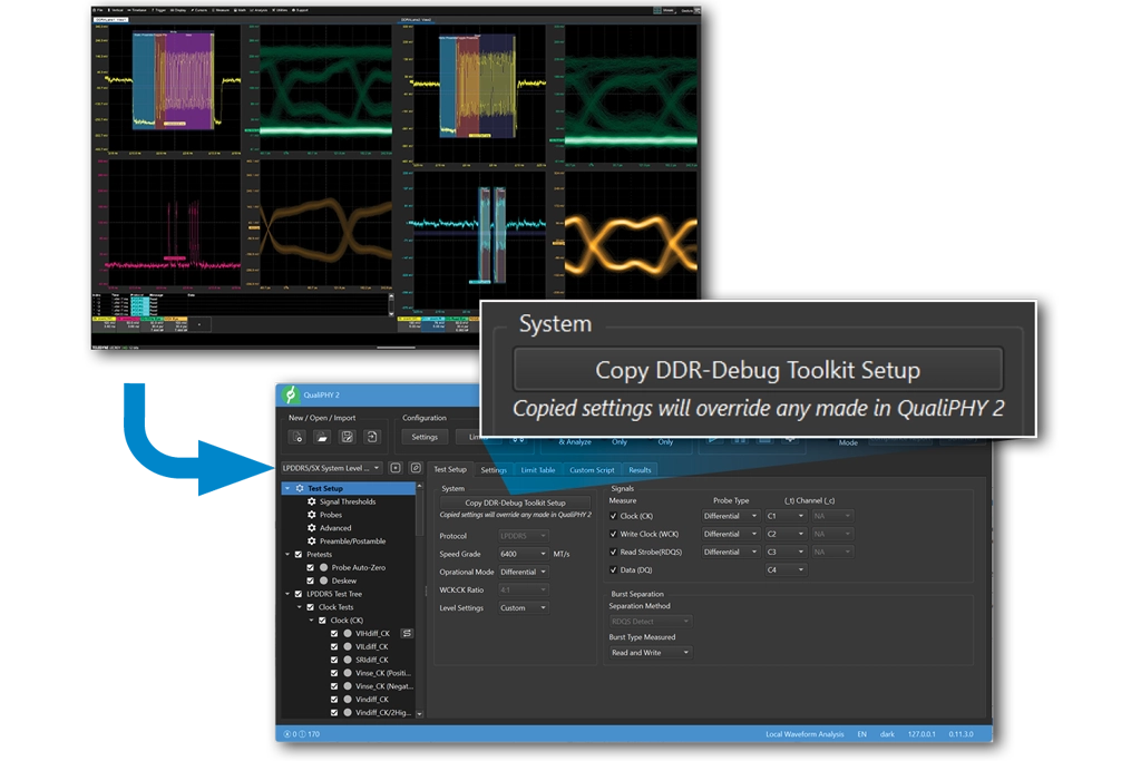
Establishing basic operation, signal checks and validating responses is foundational during board turn-ons. This means knowing if signals look correct, if the signals are communicating, if the command bus is operational, are voltage and timing settings in the right magnitude of error, do channels show both Read and Write packets. These early steps are critical and require simple, dedicated tools built just for this phase of memory design. This isn’t compliance, it’s more than that.
- Do the signals out of the DRAM (Read) or Controller (Write) look correct?
- Are initial voltage and timings details in the right locations?
- Is the command bus communicating correctly?
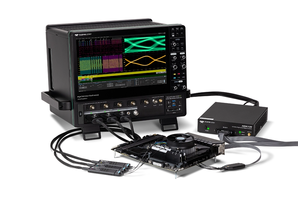
Minimizing probe and interposer impacts on your design is critical to maximize DDR signal quality into your oscilloscope. Teledyne LeCroy DH Series Probes are low-noise & low loading active probes with solder-in tips and QuickLink adapters. An interposer can further enhance signal quality by locating the test point close to the ball of the DRAM. Then, the probe and interposer combination can be de-embedded with Virtual Probe.
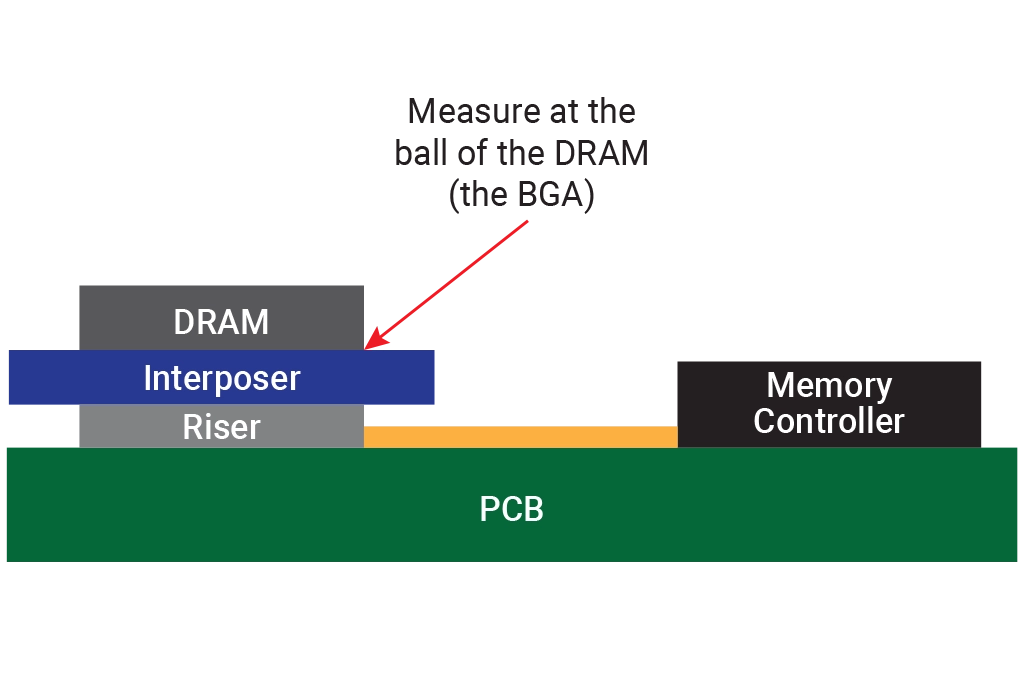
JEDEC requires DDR measurements be performed at the ball of the DRAM (the BGA), or test location #1 in the image. If your probe location is currently at #2 (interposer) or #3 (mid-bus or at a VIA) the probe location can be moved virtually before beginning DDR validation or measurements.
- De-embedding .2SP, .3SP and .6SP S-parameter files accounts for T-points with interposers and risers.
- Virtual Probing can move the probe point to the memory controller to analyze stressed Read packets.
- Remove issues caused by mid-bus probe locations
- Read Blog Post Tutorial on Virtual Probing
Probing setup errors, such as reflections, can be confused with DDR design quality. Teledyne LeCroy’s Virtual Probe @ Receiver can be used to eliminate reflections and give you a better picture of your actual DDR design performance.
- Remove termination problems with Virtual Probe at the receiver (VP@RCVR).
Teledyne LeCroy's HDA125 Logic Analyzer probes DDR command addresses digitally and conserves analog oscilloscope channels for other signals. DDR protocol decode and trigger can be used on these digitally probed signals to isolate DDR activities and data signals for faster debug. The HDA125 Logic Analyzer supports the highest 8400 MT/s DDR5 CMD address lines for decode and triggering.
- Industries only Decode & Trigger up to DDR5
- Decode JEDEC's Command Truth Table
- Perform better R/W separation, the command bus knows the packet locations
- Overlay R/W Visuals on Channels