Radar Signal Analysis With Oscilloscope Demodulation
Learn how oscilloscope demodulation and FFTs reveal radar pulse envelopes, Barker-coded phase modulation, chirp behavior, and frequency content.
Learn how oscilloscope demodulation and FFTs reveal radar pulse envelopes, Barker-coded phase modulation, chirp behavior, and frequency content.

This article explains the expected behavior of on-die power rails during CMOS switching events, including PDN current flow, clock-edge noise, and asymmetric current draw between switching and latching operations.

Learn how oscilloscope histograms help characterize component specifications by comparing propagation delay, mean, standard deviation, and measurement spread under different conditions.

This article explains how the inductance of passive probe ground leads can dramatically reduce effective bandwidth, distort measurements, and introduce resonance and frequency-response errors.

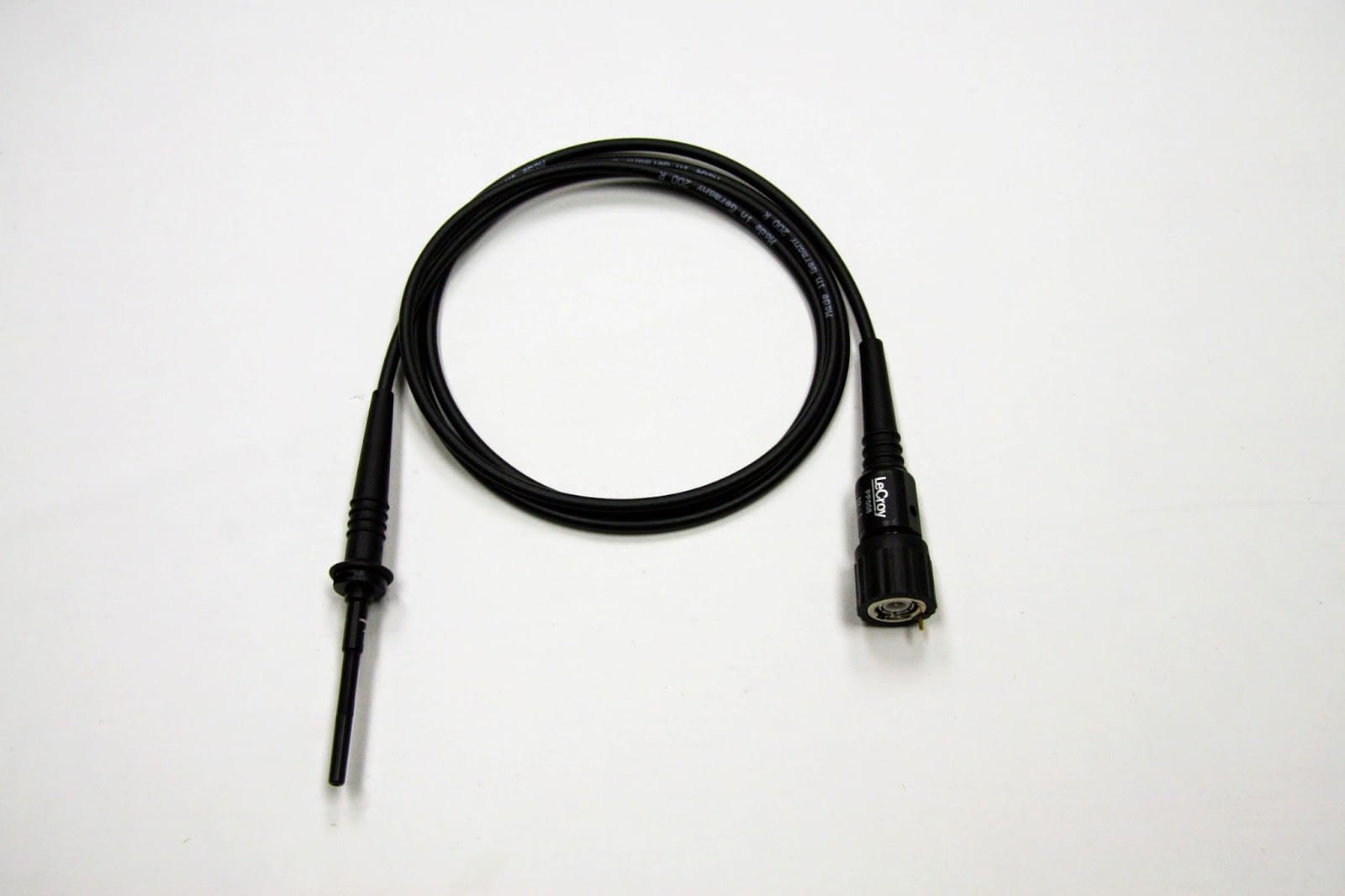
When you open the box containing your shiny new oscilloscope, one of the items you'll likely find inside is a set of basic 10:1 passive probes (Figure 1). Those probes have a ground lead that you'll likely want to use when you make measurements. Your probe has a bandwidth specification that's in the 500 MHz range; that spec was obtained at the factory with a specialized test jig having a specific ground inductance and source impedance. Now, the way in which you connect your ground lead can have a big impact on the real-world bandwidth and response of the probe.
A glance at the probe's datasheet will show you its input resistance and capacitance. For a probe with a 500-MHz bandwidth, typical values are C = 9.5 pF and R = 10 Mohms. But one spec that's missing from the datasheet is ground lead inductance; that's because there are numerous ways in which people choose to ground their oscilloscope's probes.
The most common way to ground probes is by using that long ground lead with the alligator clip at its end. However, this could create a ground loop inductance larger than 200 nH, which can greatly compromise the probe's performance. The equivalent circuit model for a probe grounded in this way is shown in Figure 2.
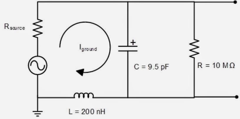
The input resistance of 10 Mohms is large enough to be ignored in most cases. What we want to look at is Iground and the effect that different inductance values will have on the response of this circuit. The voltage across the capacitor is the value measured by the oscilloscope; the voltage represented by the AC source is the signal under test. To get an idea of how these two values will differ, let's look at the transfer function of this series RLC circuit, or the ratio of the voltage across the capacitor, Vc, to the voltage source, Vs. We obtain the transfer function by dividing the impedance of the capacitor by the sum of all of the impedances.
Using the definitions shown here,
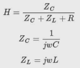
We obtain the transfer function:
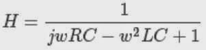
By hand-picking optimal values for R and L, we can get the probe's 500-MHz bandwidth. And one can get close to this performance by using Teledyne LeCroy's ground blade or ground spring probe accessories, which may have an inductance of 10-20 nH. It's also important to consider the ground-loop issue and connect to a close-proximity, low-inductance ground point on the DUT. Using copper foil can help with achieving a nearby ground connection and to minimize the length and inductance of the ground connection (Figure 3).
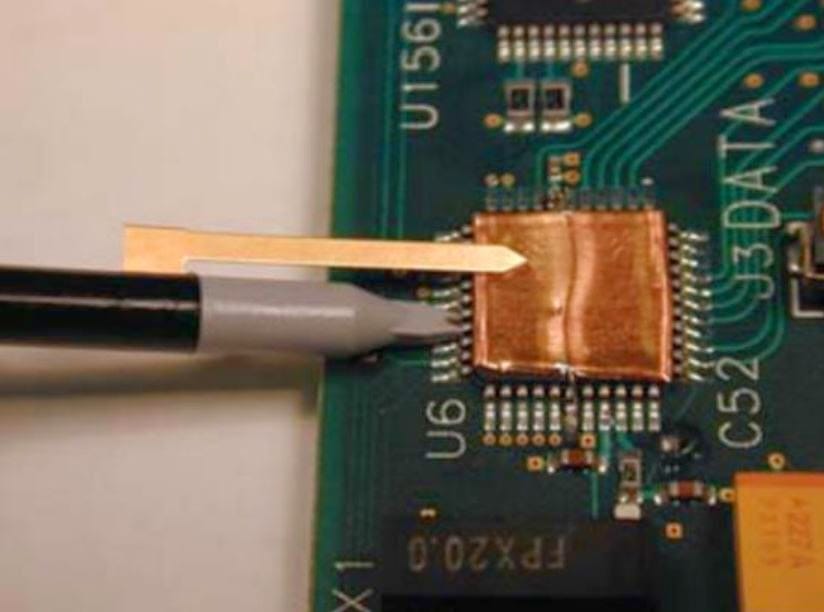
In most cases, though, the ground connection people use is the long alligator-clip lead. What effect does this have on the bandwidth and frequency response of the probe? Well, for starters, if we use this lead, the ground loop of Figure 2 will be at least 10 inches long. If we take 20 nH/inch as a rule of thumb, we can calculate the inductance at about 200 nH. Using a Teledyne LeCroy ArbStudio function generator with a source impedance of 50 ohms, plugging these two values into the transfer function yields this plot (Figure 4):
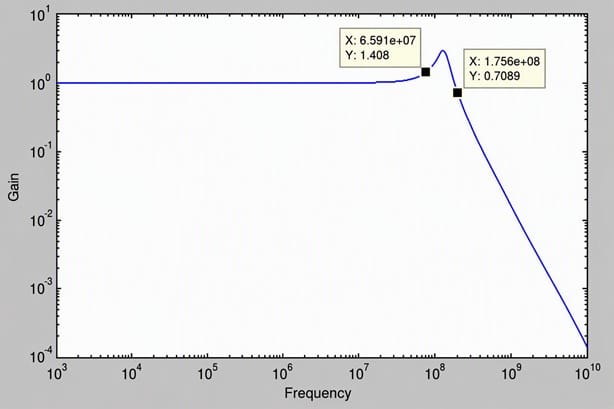
We can see that the added inductance has moved the -3dB bandwidth of the probe from over 500 MHz to about 175 MHz. Not only that, but the probe's resonant frequency was pushed well within its bandwidth to about 115 MHz. At 65 MHz we can still see an error of 40%. In fact, to keep the error under 10%, we need to limit the frequency to 35 MHz.
Copyright © 2020-2026 Teledyne LeCroy. All rights reserved. All original content, including text and photos, is the property of Teledyne LeCroy and cannot be reproduced without expressed written permission.

Learn how tip inductance from mini-grabbers and long ground leads reduces 10x passive probe bandwidth and adds peaking and ringing to measurements.

This article explains how 10X attenuating probes reduce signal-to-noise ratio, amplify oscilloscope noise-floor limitations, and compromise low-level power-rail measurements.

Understanding the internal design of a 10x passive probe reveals the trade-offs that affect signal accuracy, bandwidth, and noise performance.

Knowing a probe’s dynamic range, differential limits, and common-mode voltage helps ensure safe and accurate measurements in high-voltage circuits.
